University of Toronto :: Department of Computer Science :: Geometric Representation for Computer Graphics
Milling Machine
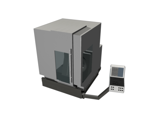
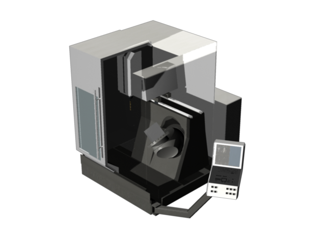
The
functional object modeled is a milling machine. The current work is
based on previous one I have done during an internship in 2001. There I
visualized a similar machine based on the CAD data of such a machine.
 |
 |
Objective
My personal objective was to explore the state-of-the-art of modeling with parametric patches, especially Non-Uniform Parametric Bi-Spline (NURBS) surfaces. Unfortunately, modeling with NURBS is still a challenging task -- more than 30 years after NURBS have been introduced. The interaction techniques are mostly based on the underlying mathematical description, for example the control points, which can be counter-intuitive and inefficient. Another issue is the modeling of object with non-contiguous surfaces. For example a simple box consists of six surface patches which complicates modeling significantly if the box has to be manipulated as one object.Investigating the capabilities and limitations of boolean operations for modeling has been another objective. Although these are very powerful and simplify modeling in many cases, my experience in the past has been that there accuracy and capability to reconstruct a valid surface representation are limited. This is still true today. After a certain number of operations, Maya is no longer able to define a valid surface representation. These limitations for boolean operations also holds for polygonal models but are worser when modeling with parametric surfaces. This, for example, caused the short time for the milling in the animation below.
Functionality
The final model of the milling machine allows to manipulate the parts of the machine which are also non-rigid in the real world. These are| Door | Translation in X-direction |
| Commando Station | Rotation around Z-axis |
| X-carriage | Translation in X-direction |
| Y-carriage | Translation in Y-direction |
| Z-carriage | Translation in Z-direction |
| NC desk | Rotation around axis perpendicular to seating of the desk |
| Workbench | Rotation around local up-axis |
The keys on the bottom of the commando station can be used to move the milling cutter (MC) and mill. The mapping of keys is as following
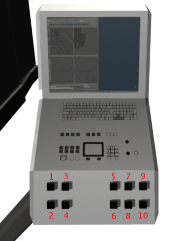 |
|
If the milling cutter intersects the workpiece material is cut as in reality. To achieve this a boolean operation is performed after each X-,Y- or Z-movement of the milling cutter (but not after a rotation of the NC desk or workbench).
Downloads
Maya project: milling_machine.tar.gzAnimation of the milling machine: milling_machine_320_240.mp4
Limitations
- Then loading the Maya file, sometimes the script file containing the button-press callback cannot be found. It can manually be loaded from './script/interaction_callback.mel'.- Maya cannot reconstruct the workpiece after the boolean operation.
- No collision detection between milling cutter and NC desk.
- No force computation, for example to checks if the force on milling cutter is to large and it should break.
References
- Model of Milling Cutter (in ./models)- Booklet for milling machine (in ./references)
| lessig@dgp.toronto.edu | dgp Lab || October 2005 |